Monday, September 17, 2018

Steampunk Protostar #9, The Plastic Tail Section

Now that the core of the engine mount is completed, the next step is to prepare and install the plastic tail cone that came with the kit. 

After carefully cutting it away from the molded assembly per the instructions, the unit requires a little bit of work before it can be installed on the motor mount.  None of these steps are addressed in the instructions, by the way, but are pretty intuitive.

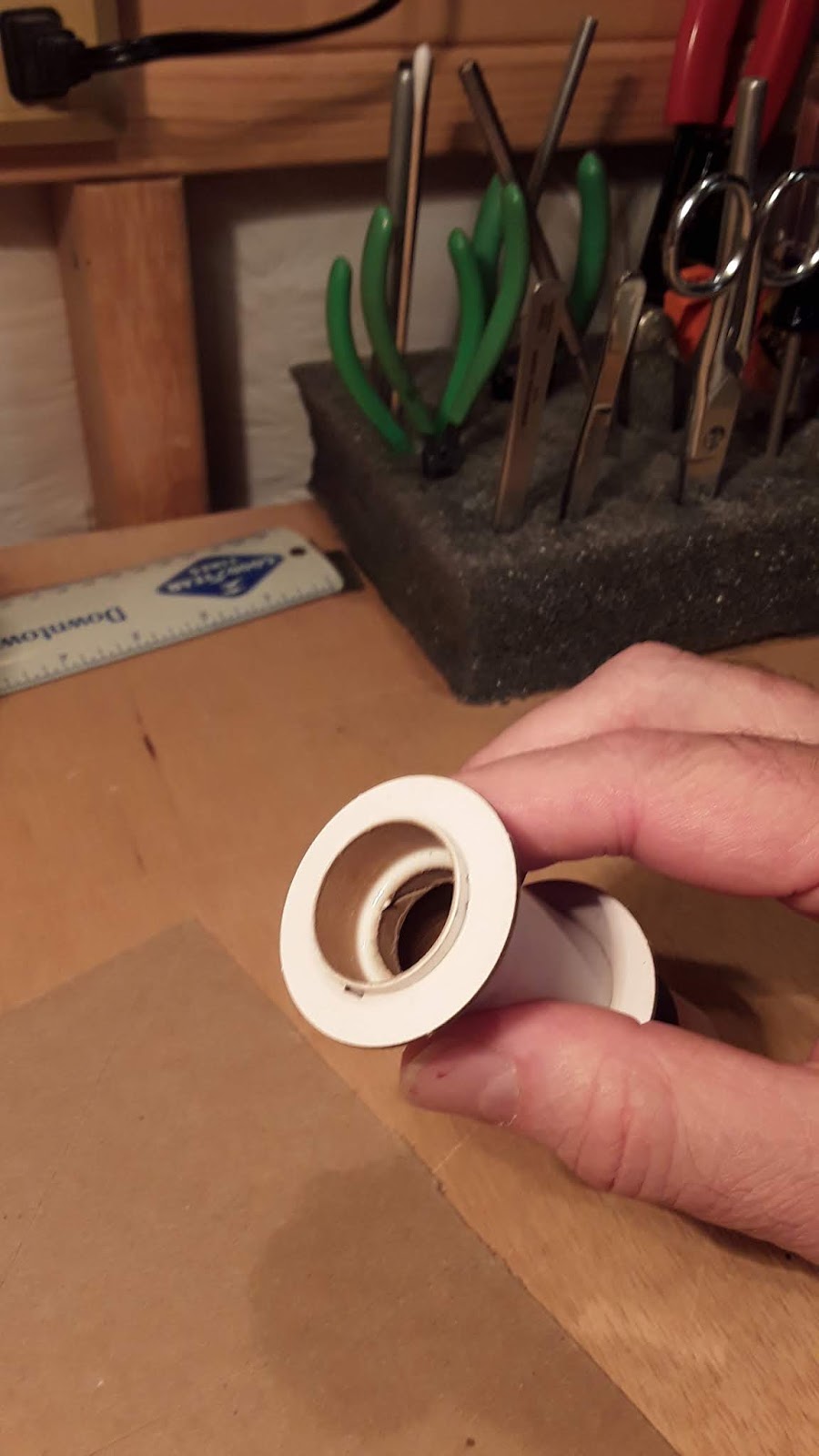
First the cavity for the engine hook must be widened with a needle file so that the hook can fit and move freely when the tail section is installed.

Second, the plastic 'flange' at the tip of the tail cone most be removed so that the unit can fit cleanly over the engine tube.  I used a Dremel rotary tool equipped with a drum sanding attachment followed by a curved needle file to fine tune.


Now is the time to dry fit the tail cone to its position on the engine mount to make sure everything works.

If all is well, the tail can then be CA'd to the engine mount per the kit instructions.  The main point to watch here is to make sure the top of the tail cone lines up precisely with the aft paper centering ring.


The final operation for the tail cone is to remove the unsightly molding seam lines.

This can be accomplished quickly by using an X-Acto knife as a scraper. 

Holding the blade at a 45 degree angle, the blade is drawn backwards (away from the cutting edge) along the seam line.  It effectively shaves off the excess plastic. 

A little more work is done with some fine sandpaper to smooth things out nicely.

On this build I am not going to worry about any depressions along the seams, as the lines will later be completely hidden by 'Steampunk' detailing.  If I were building the Protostar as stock, I would be using some thinned CA to fill the seams and sand smooth.

Friday, September 14, 2018

Steampunk Protostar #8, The Motor Mount

The next phase of the Steampunk Protostar build is the motor mount/tail sub-assembly.

To start off, the main mount parts are put together in accordance with the kit instructions, so I won't go into a step-by-step treatment here.


I'm still not positive about whether I like the new Estes kit instruction format.  The illustration-only presentation is OK, but it tends to leave out a lot of construction details (and potential pitfalls) that accompany each step.  I sometimes try to place myself in the shoes of a novice model rocketeer who might not have a lot of building experience attempting to navigate these directions and build this model by pictures only.
 
Iffy, at best. 
 
This method might work well with LEGO sets, but for a free-flying model meant to be powered by fairly hefty rocket motors - not so much.

Anyway, off of the soapbox and on to the model...

The only thing I did different with the basic mount is to move the forward centering ring back about 3mm.  This allows for the application of a good filleted glue joint between the ring and motor tube.
The kit instructions show the ring glued flush to the very end of the tube.


As for the engine hook retainer ring and aft centering ring, it is extra important to place them EXACTLY at the dimensions specified in the instructions.  The location of these parts will dictate the proper placement of the plastic tail cone later on.  Again, it would be helpful if the instructions had a short written blurb stressing the importance of this small detail.

The final touch to the basic mount is to apply a good glue 'fillet' to the interior engine block/motor tube joint.
Build 'em strong, sez I....


Next post will tackle the prep and installation of the tail cone and a few other extra details (that aren't in the instructions).

Thursday, September 13, 2018

Steampunk ProtoStar #7, Still More Fin Prep

"The power of the Mighty D Engine compels you....The power of the Mighty D Engine compels you....The power of the....."

Oh !....Yes.....AHEM......Protostar......

The next step in fin prep/construction is to glue the two halves of each unit together.

This is done using double glue joints after which the fins are placed between sheets of waxed paper and a couple pieces of plate glass. 


A weight is placed on top to keep everything flat and in place until dry.

Once the completed fins are dry, they get another quick overall sanding.

Here are the completed fins.  They will be set aside while other Protostar assemblies will be worked on.


Wednesday, September 12, 2018

Steampunk Protostar, Part 6 - More Fin Prep

Now that I have finished posting about re-unions, Flatcats, and Canopii, I can finally get back to the Steampunk Protostar build series that was started way back in June...

Today's rocket building exercise involves a continuation of preparing the Protostar's fins.
This step consists of providing the first bit of  'Steampunk' detailing - specifically, poking a series of holes in the fins.

I have no idea what these holes are for, other than serving as fancy detailing. 

The Victorian design engineers probably know, but they're not divulging any secrets!

I'm only the project's construction grunt.  Those other guys are probably off somewhere in their 'smoking parlor' tipping back a glass of Sherry and engaging in 'merry talk' and 'sallies of wit"!

Anyway...the fins.....

The first step is to mark out the hole locations.  This is done by making a cardstock template of the upper fin section, drawing a guideline using a  French curve drafting tool, and spacing the hole locations.  (Wait a minnit...French curve?  This is supposed to be strictly an English build!)


The four hole sizes will be graduated from 5/16" diameter to 1/8" in 1/16" increments. 

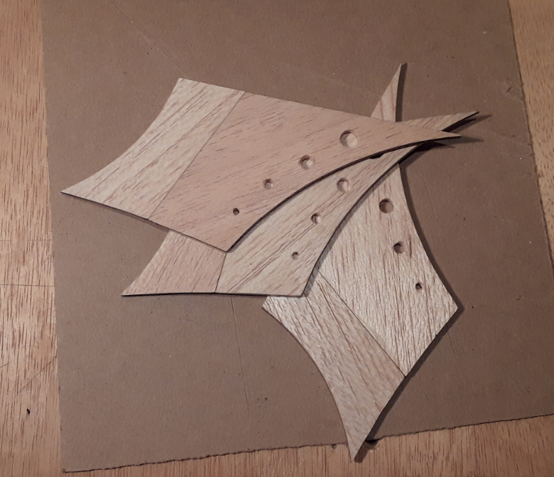
Here, the 3 upper fin sections and the template are stacked, aligned and pinned into position, ready for drilling the holes.


In the interest of keeping this build true to the Victorian-era spirit, I had originally intended to use one of my antique 'egg-beater' hand drills to  make the holes in the fins.


But, for the sake of precision and accuracy, I opted out, and resorted to the electric drill press instead.


A plywood backing board placed under the bottom fin helps to prevent drill bit 'tear-out'.

Here is a pic of the drilled fins. Balsa wood is generally very unforgiving with the use any kind of power tools, so there is a bit of tear-out material in the holes that must be cleaned out and smoothed.  Sandpaper and fine needle files will be used here.

Just noticed another interesting vintage tool appearing  in the photo's upper left corner.  Yep, kiddies, a good old fashioned scratch awl can be effectively used in model rocket building!


Tuesday, September 11, 2018

Back In The Day, #14 - It''s Deja Vu All Over Again!

As I have been wrapping up the final details of the recent Canopus-2 and FlatCat rocket builds, I took some time to descend the dark, dank staircase that leads to the secret BlastFromThePast rocket la-BOR-atory, activate the hidden secret bookshelf and pull out a large secret notebook labeled  'Old Fleet Model Rocket Inventory'.
This massive loose-leaf tome was put together back in 2016 and contains data sheets, any existing photos, and flight information for every single model in my old timey fleet.
Since I had very few photos of my earliest rockets, and flight data recording was very sporadic in those days, it was quite a task to piece together the history of those first 103 model rockets. 
Much of the information was gleaned from memory, which at my age is...well, you know....

Anyway, I discovered something very interesting  - the model rockets with fleet numbers 8 and 9 were - Canopus 1 and a FlatCat boost/Glider, both built in 1974!

44 years later, I find myself building new versions of the same models in exactly the same sequence.

Fleet #8 - Canopus


I did not have any photographs of this bird, but did, at some point, sit down and make a half-scale drawing of the model which I was able to salvage (peel) from an earlier scrap book and mount in the new notebook. 

This drawing even shows the color scheme of the original rocket.  Looking back, sky-blue and black were probably not the greatest paint choices for a rocket that was expected to reach a considerable altitude.

I have absolutely no flight data on the rocket, other than it was launched five times.

The final flight was dated 15 June, 1974.  It took place at a demonstration launch hosted by a fellow Colorado Springs rocket club, the Rapirhawks, headed by Warren Layfield. 

The only notation I have on this flight is "Model was lost".

I'm reasonably sure that a couple of the Canopus' flights were in cluster configuration.

A rocket engine inventory/usage log for 1974 indicated the use of four 1/2A3-0T engines. 

At the time, there were no other rockets in the fleet that would have used such engines, so I surmise that they were employed to help boost the Canopus on at least two of its flights.


Fleet #9 - FlatCat B/G

Built in 1974 from an original MPC kit, the FlatCat did not see its first launch until 11 June, 1975.
The bird was flown as built using a B6-4 engine.  A flight log states that the flight was somewhat successful, but the engine delay was too long for any lengthy glide phase.

Later on, the model was modified into a sliding pod rocket glider.  The dual vertical stabilizers were removed and replaced by a single center v-stab in the manner of more common glider designs.

The model was flown four more times with varying degrees of success:

4 April, 1976 - B62
13 November, 1977 - B4-2
22 January, 1978  -  B4-2
6 August, 1978  There is no flight data on this one other than the notation that the model "crashed and was destroyed".

This is the only photo I have of this bird, showing it in R/G configuration:

 
CHEERS!


Monday, September 10, 2018

BAR Fleet #117 - FlatCat Boost/Glider


Scratch Built From Published Plans


Designer:  G. Harry Stine
Type:  Conventional Pop-Pod
Boost/Glider

Stages:  Single
Engine Type:  18mm
Recovery:  Streamer, Glider
Length:  47.5cm
Weight Empty:  25.0g
Nose Cone:  Short Elliptical
Color Scheme:  Yellow, Orange, Red, and Black with black and chrome silver Trim.

 Glider
Length:  40.6cm
Wingspan:  33.3cm
Weight:   17.6g

 Pop-Pod
Length:  17cm
Diameter:  18.8mm
Weight Empty:  7.4g

Date Completed:  8 September, 2018

Saturday, September 8, 2018

FlatCat Boost/Glider Build, Part 15 - Finishing Up

Now that the paint on the pop pod is dry, it gets some fleet number decals applied.


It's funny to think that this project is only the 117th model rocket I've ever built for my personal fleet.  This quantity includes the 103 birds built between 1973 and 1984.  I've only constructed 14 new models since I became a BAR in May 2016. 

Not an outstanding output.  Perhaps it's because I'm going for quality rather than quantity. (Yeah, Right!).

Of course, I did build many other rockets besides the ones for my personal fleet.  Most of these were birds used by the Skywatchers/ROMAR club for public demo launches back in the day.   I also participated heavily in Estes' build-up program in the late 70s - early 80s.  This usually involved building half a dozen of the same kit side by side.  On a few occasions, I had 3 different build-up kits on the bench to fill one order.  That was 12-18 models being constructed simultaneously!

Anyway, back to the FlatCat:

The pop-pod gets a sealing coat of Gloss Sauce....


...and an application of CA inside the top of the body tube.


Next, the shock cord system is built out of a piece of manila folder stock and a length of cotton string, as specified in the magazine article.

For the shock cord mount, I use a 3-slit method on a flat piece of card stock.  I don't like using tri-fold mounts on any tube smaller than BT-50 because of the bulk.

This mount is very similar to those found in the old MPC kits, though I believe theirs had pre-punched holes.

Now, the pod gets equipped with its very own dedicated 1x16 plastic streamer.


Before permanently gluing in the nose base, it's time to perform balance trimming of the entire model for the boost phase of flight.  The nose is not yet assembled, just in case I need to insert some clay weight.

With the pod's shock cord, streamer and nose in place, I insert a new A8-3 engine into the tube.
The FlatCat will most likely be flown on B4-2 engines, but balancing the model using a lighter A will give it that extra margin of forward stability ballast.

The idea here is to ensure that the model's boost configuration CG is located ahead of the wing leading edge.

The model's CG fell approximately 3/4" ahead of that point.  No trim clay required!

The nose base can now be glued in.

And, I finally have a fully completed FlatCat -  ready for the launch pad!


Cheers!