Following nearly an entire summer and fall season of not flying any model rockets, conditions and circumstances were finally ideal to schedule a Colorado Front Range launch. Why this long hiatus from launching? Many reasons: personal travel and illness, constant local windy conditions, lengthy periods of fire danger restrictions, and smoke pollution from both Colorado and out-of-state wildfires.
It all ended this past Friday, when weather forecast models called for dead calm air along with the temperature at right around sixty degrees. In the previous week, Denver got hit with about a foot of snow, which provided enough moisture to end all burn restrictions. Perfect!
Even better, we could again enjoy the larger field at Dove Valley Regional Park in Centennial. This area had been off limits for use during an 18-month period beginning in March of 2023, due to park renovation and construction.
Being the first to arrive on the scene, I just had to take a photo of the spacious expanse of manicured turf spread out before me:
It wasn't long before the other troops began arriving. Joining me today were Jim Gazur, Mike Goss, and Mike Perreault.
In short order, launchers were set up and an interesting variety of model rockets were 'unsheathed'.
Mike Perreault had all of his models to be flown spread out on the turf. An impressive array, indeed. All were pre-prepped and ready to hit the skies.
I started things off with flight #17 of my flagship EAC Viper. The model flew straight up on a B6-4, deployed it's red, square, four-shroud-line para-sheet (a la Model Missiles, Inc.), and descended slowly in the still air. I jogged underneath it and easily caught it before it touched the ground. A perfect start to what would be a great launch session.
This was immediately followed by Jim Gazur's Spacemonkey V2
(BLOGGER's NOTE: Following every launch session, I usually get a 'launch synopsis' email from each of the other participants. These write-ups always provide interesting information about their various flights. Rather than spend the time re-copying or re-wording these comments, I've found that it is better to cut and paste each rocketeer's model and flight descriptions in their own words. I have done this to some extent in past Launch Date posts and the results seems very satisfactory.)
Take it away, Mr. Gazur:
"Spacemonkey V-2 plastic model conversion on a research motor
in an Aerotech 24/40 case. The motor tested out at 43.8 Newton-seconds
with a 15 Newton average thrust. The average thrust is a bit deceiving as
I used a "moonburner" core configuration yielding a 70 Newton peak
thrust at 0.13 seconds in order to get heavy models off the pad. I don't
normally do "effects" propellant, but when the price of Ammonium
Perchlorate quintupled a few years ago I bought a bunch of Strontium Nitrate,
which produces the red flame. Yes, amateur rocketeers name their
experimental propellants, so I've dubbed this one King Crimson."
(Jim, does the propellant name bear any reference to a certain prog-rock band?)
After troubleshooting and fixing some issues with his launch controller, Mike Perreault had his first model on the pad ready to go:
"First flight was the ’Not So Hi-Flier’ … making
it’s second flight on an A10-3T …. a perfect launch and recovery."
Soon after that, Mike Goss had his first flight of the day ready on the pad:
"Rocketman Miss Riley 1/4 scale, C11-3, Ejection just
before apogee, great flight."
Since the weather forecast for the day had been so favorable, I packed along a number of glider models for the launch session. The first of these to be flown was the Edmonds Deltie Airshow, on its maiden flight. I'd been anticipating the launch of this three-glider contraption for well over a year.
Against my better judgement, I selected an A8-3 motor to power the model.
 |
| Yours Truly Blogger prepping the Deltie Airshow |
At ignition, my A8-3 trepidation proved to be well founded - the model flew straight up to about 100 feet, turned over and started streaking toward Terra Firma! As the bird(s) fell, I envisioned a spectacular 're-kitting' that would spew balsa splinters everywhere.
To everyone's surprise, the ejection charge went off when the model was around thirty feet above the ground! The three gliders separated, and the booster para-sheet deployed. All of the gliders transitioned into glide phase, but their durations were very short, due to the fact that they straightened out maybe five feet above the turf.
 |
| The Deltie Airshow shortly after ejection. Photo by Mike Goss |
To my delight, all four of the vehicles were recovered without showing even a scratch. The Deltie Airshow would fly again! If nothing else, this flight proved to be the most amusing of the day.
In quick succession, Mike Perreault had his next two birds on the launcher and in the air:
Second flight was the ‘Mini Goblin’ making its maiden voyage on an A3-4T. Great flight with a short recovery walk."
"Third flight was an Estes Doorknob, also making
a maiden flight. It launched on an E16-6, which proved to have a bit too
long of a delay. An E16-4 would be preferable but was not available.
Had a perfect liftoff …. straight and stable, arched over and fell for a
tense few seconds before a successful deployment and safe landing."
About this time, some newcomers showed up on the flying field. These turned out to be the newest folks to recently join our Front Range rocketry group, Rich Wallner and his wife, Shelley.
Rich didn't bring any birds to fly today, but promised he would have some for our next launch session. We are very pleased to have the Wallners on board!
Back on the firing line, Mike Goss had his next bird on the pad:
"Estes Hornet reissue, B4-4, Great flight!"
More great launches courtesy of Mike Perreault:
"Fourth flight was a Boosted Bertha … my first attempt at a two stage launch. The booster held a C11-0 and the sustainer held a B4-4.
A successful launch, boost and recovery."
"Fifth flight was the maiden flight of an Estes Cold Power Marauder clone, leaving the pad on a C6-5. Perfect flight and recovery."
Shortly after, Jim Gazur had his next model prepped and ready for launch:
"This model is the 'Snowbird', my waterproof fiberglass rocket, on
the same research motor which gave quite an authoritative boost."
"The
chute didn't eject, but the nose cone did, so it came down sideways and didn't
sustain any damage."
My next flight was a redeux of the Deltie Airshow, this time powered with a B4-2 motor.
Again, the model flew very straight and considerably higher than the first attempt.
At the prescribed time, the ejection charge fired and all three gliders split off, transitioned, and began well-trimmed glides! The booster rocket para-sheet deployed fully, as well.
It was quite a spectacle to witness all four components descending slowly. An 'airshow' indeed. It took two other participants besides myself to help with tracking the gliders and seeing that they were successfully recovered. All gliders touched down within the park boundaries and were returned intact. Excellent flight!
Soon thereafter, Mike Perreault was ready with some more birds. There is something to be said for pr-prepping models the day before a launch. He was able to bring a lot of them and keep 'em going in quick succession:
"Sixth flight was my Der Big Red Max … on its maiden flight. This was loaded with an F16-6 … which was too long a delay.
An F16-4 would have been the choice, but was unavailable. The flight was straight and stable. It arched over and fell for a tense couple of seconds and then deployed the chute. Sadly, the Estes chute came apart (stripping all six lines) and Max came in for a bit of a hard landing. One fin was damaged along the fillet. Repairs will ensue."
"On a good note, it did stick the landing."

"My seventh flight was the maiden flight of the Kepler. This is an Apogee Components ’Tarmon’ design that was upscaled to BT55.
It left the pad on a D15-5 for a perfect flight and recovery. The rocket will be getting final decals and clear coat in the near future."
Mike Goss was up next for his third and final flight of the afternoon. Sadly, he only had an hour available to break away from his workplace to fly a few rockets. Another case of model rocketry being interrupted by the mundane things of life!
"This model is the Fliskits Celtic Thunder, flying on a B4-4. Ejection at apogee.The model sustained a small
nose dent from a fin. The streamer didn't work well, maybe a small parachute?"
Jim Gazur soon had his next rocket hooked up and ready:
"Estes Taz on an A8-3. Nominal flight, and so
much fun I flew it again on another A8-3—landed very close to the pad. I
don't know if Estes finessed the design, or it was just the light winds, but
the motor pod and airframe came down very close to each other both times,
making for an easy recovery—not nearly as challenging as, for example, an
Edmonds Deltie Airshow....."
Unfortunately, we didn't get any photos of either of these flights.
Since it was such a good day for flying gliders, I decided to pull the Wasp B/G out of the box and give it a go:
Boosted by a 1/2A6-2 motor, the model ascended very straight.
The glider separated, but was poorly trimmed. Instead of gliding, it spiraled to earth in a very tight right turn. All was recovered unharmed.
Another model was soon ready on Mike Perreault's launcher:
"Today's eighth flight was the maiden flight of an Estes Cold Power Shark clone, leaving the pad on a B4-4. Perfect flight and recovery."
My next model to be flown was the scratch-built Astron Orbital Transport. I just can't get enough of them gliders, folks!
The model boosted very straight on a B6-4 motor, with ejection occurring just after apogee. The orbiter separated and settled into a nice slow glide, describing a very wide right turn. When it landed, it was headed straight for the launch area. Someone made the comment that it looked as if the glider was under radio control! Another perfect flight turned in by the OT.
By this point, Mike Perreault and myself were the only two rocketeers with models left to fly.
Here are Mike's next two:
"Flight number nine was an Estes Goblin, flying on a D12-5. This was the first flight after a fin reattachment (prior hard landing).
A perfect flight and recovery, though a long walk was required as the upper winds had started to pickup. The flight left the park, landing in the center median of the adjacent roadway."
"Tenth flight was the Mini Arcas, making its
second appearance. Filled with an A3-4T it gave a perfect flight and a
close recovery."
A two-stager was the next model to be flown from my on-field arsenal. This is an Estes Viking boosted by a specially built open-gap booster stage. The tandem flew on an A8-0 / A8-5 motor combo.
The model took off very straight and staged perfectly. The Viking flew to a very impressive altitude, being nearly lost against the very bright high cloud cover. It was recovered safely via crepe streamer. All parts were successfully recovered with no damage. Great flight!
Next up was another flight from Mike's launcher:
"Eleventh flight was the Mini Honest John, on an
A3-4T. A nice flight and recovery."
Next, it was my turn again...this time it was a flight of the only D-powered model I had packed along for the day, an Estes Cherokee-E.
Liftoff for a great, straight-up flight on a D12-5 motor.

The model landed under parachute on the north berm of the park perimeter and was recovered intact. I have yet to fully air this model out with an E motor. On its next outing, perhaps.
And now, presenting Mike Perreault......!!
"Twelfth flight was the ‘Der Red Max’, flying on a C6-7. Great flight. No picture on the pad but did get a shot after landing."
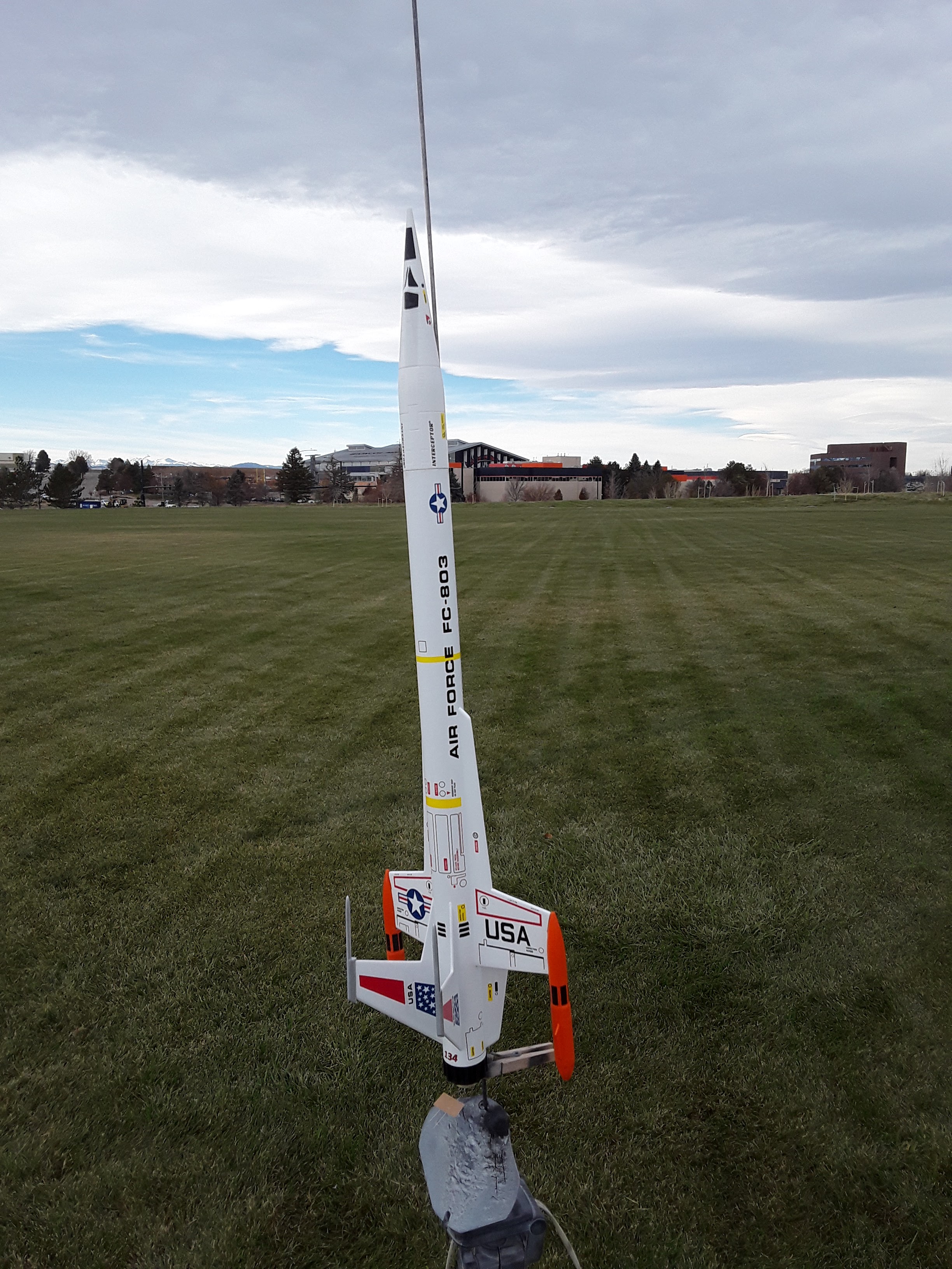
My 8th and final flight of the day went to the Estes Interceptor:
The model turned in a picture-perfect boost and coast. At ejection, the parachute exited, but did not fully deploy due to a couple of shroud lines getting tangled with the nose cone. It opened far enough to provide a safe recovery, however, and the model sustained no damage.
The final two flights for the afternoon were put up by Mike:
"My thirteenth flight was the ‘Mini Max’ making it’s
second flight on an A3-4T. Great flight."
"The fourteenth and final flight of the day was an Estes
Hi-Flier, stuffed with a B4-4. Straight and true, landing about 10 feet from the launch pad."
Extra note on this last flight - Mike's Hi-Flier landed with its nose cone a mere 13 inches away from the red crepe streamer wind marker that can be seen in some of the above photos. A great 'spot landing' touchdown! -Ed
With this said and done, it was time to pack up and head home.
It was an absolute perfect "Red Letter" day for flying model rockets at Dove Valley. Out of the 29 flights made, only one ventured past the park perimeter, attesting to the superb lack of wind. The only detrimental aspect of the session was the high, bright cloud cover that prevented us from seeing the delay smoke trails on the majority of the flights. We managed, though, as shown by the perfect recovery record. Most of the models landed within an easy walk of the launch area.
Best of all, there were no major mishaps. Aside from one broken fin and a shredded parachute, all the models came home intact. Kudos to the team!
I will leave you with today's odd/unusual/off-the-wall photograph:
When I recovered my Interceptor from its flight, I noticed that a large piece of recovery wadding had descended with the model.
To my surprise, I found that, during the violence of the ejection event, the wadding had impaled itself on the pointy antenna of one of the model's fins !


.jpg)
.jpg)