Pages

All Of My Blog Pages

Saturday, March 23, 2024

Artemis I, Part 9 - "A Trick of the Tail"

 That's the title my all time favorite Genesis album from 1976.

It also applies here with the Artemis build as I embark on the model's tail piece, which might be a bit tricky to engineer into position.

The piece is designed to be glued onto the rear of the main core rocket tube (where else, eh?). It also bears a lot if the small detail at the aft end of the rocket.

Since my core BT-50 motor tube protrudes a bit further than the end of this piece when installed, I will have to cut the bulkhead to fit.

A drill and Dremel tool does a fine job with that:


Here is the finished tail section dry-fitted in place...

I have decided that the four scale RS-25D engine nozzles will be retained on this model, but in order to do that, they must be cut back on the inner surfaces to clear the working BT-50 tube and protruding motor. Here are the four nozzles fitted in their locations. I've applied small guide marks with a Sharpie marker to show where the parts must be cut back:

The nozzles will attach to the tail base plate via two locator pins apiece.  Each nozzle is finger-held while being carefully trimmed back with the Dremel.  Delicate work, folks.

Here is the first finished nozzle after cleaning the edges up with needle files:

Now to make theee more just like it.

The nozzles won't be glued on until after all the parts are painted separately.

Moving on...


Friday, March 22, 2024

Meanwhile, Back At The Other End Of the Workbench...

 In between work on the various sections of the Artemis build, I have a few other small projects in progress at the far end of the workbench.

First, I managed to cut and seam-fill a section of BT-55 body tube to replace the damaged one on the Estes Solo model that lawn-darted on its last flight. The tube also got fitted with a set of launch lugs.

Yesterday, I took advantage of some very nice weather outdoors, so the tube received a coat of primer.

While I was at it, I shot some primer on the two open-gap booster stages I had finished assembling last fall.


Over the next couple of days, these items will get sanded, painted, and made entirely flight ready.

Cheers!

Saturday, March 16, 2024

Artemis I, Part 8 - The 'Topper'

 Initial assembly of the of the nose portion of the model is quite straightforward - two molded halves to cement together topped with a very tiny nose cone to complete the escape system.

I did find that, after the cement dried, the escape motor section appeared a bit crooked. Time to break out the 'thermal assembly modification apparatus' (Mrs. BlastFromThePast's hair drier) to attempt to warm the plastic part up enough to straighten it out.

The next process in the assembly is to build a shoulder for the nose section that will fit inside the core section's BT-55 parachute compartment.

A quick check of my parts stash revealed that I had no spare 55-sized stage coupler, so this was going to require an improvised approach.

Normally, a short piece of BT-55 slit lengthwise and cut down to fit inside a 55 tube can be used as a makeshift coupler.

But, I happened upon an different solution...

As a consummate scrounger, I always hang on to any cardboard core tubes from gift wrap rolls and food service products.

To my surprise, one of the tubes in my stash just happened to fit nicely inside a BT-55!

Out came the tube cutting rig again...

The fit inside the 55 was a tad bit loose, so a strip of printer paper was glued around the coupler, giving it enough diameter to fit snugly.

Next, a bulkhead was cut from a sheet of 1/6" basswood and epoxied in place.

To center the coupler in the plastic nose assembly, eight 1/16" basswood spacers were glued around the perimeter.

For the parachute/shock cord attachment point, I'm going with a section cut from a large paper clip.  Two small holes get drilled into the basswood bulkhead to accommodate the wire.

Since this part will be taking a lot of recovery deployment stresses, I deemed it a good idea to reinforce the bulkhead. For this I went with a metal washer epoxied to the inside of the coupler. This will also serve to add a bit of nose weight that I know will be needed down the road.

The paper clip wires were then inserted and bent over atop the washer. As an extra precaution, I flowed some solder into the joints to keep them attached.

Looks ugly, but it should hold...

This project has definitely morphed into a true scratch-builder's dream (or nightmare, depending on one's perspective) !

The coupler will not be glued into the plastic nose section at this time to allow the later insertion of whatever additional nose weight will be required when the model is fully assembled.

Cheers!

Friday, March 15, 2024

Artemis I, Part 7 - Constructing The SRBs

 With the core rocket assembled, it's time to turn my attention to the model's two SRBs.

These will be powered by A10 plugged motors, so the mounts will be fairly straight forward, and modification of the kit plastic parts will be relatively simple.

The first order of business is to fire up the Dremel and remove the plastic alignment pins and sockets at the aft ends of the SRB halves.

Building the motor mounts

Here I will be using the two-inch sections of BT-5 that were cut to length earlier. These each get a motor block glued in, spaced so that the motor casings will be flush with the SRB nozzle details. I am foregoing use of the music wire retainers, as the plugged motors won't have much of a kick-back. They may however, get friction taped in to prevent the casings from ejecting as the core motor continues thrusting.

I found that I was out of stock on manufactured BT-5 sized motor blocks, so a couple of spent casings, a razor saw, and a bench hook remedied that problem.. 

Why I save cereal boxes...

They come in handy for making some scratch-built rocket parts.

In this case, pieces cut from a box panel are the perfect thickness for fashioning the required centering rings.

Glue-up time...

As with the core rocket assembly, I am using 30-minute epoxy to install the motor mounts.

Then working quickly with more epoxy and the required amounts of plastic cement, the SRB halves are pressed together and secured with rubber bands.

Oh, and must not forget the tiny SRB nose cones...

More to come!

Thursday, March 14, 2024

Artemis I, Part 6 - gluing up the SLS Core Rocket

This is a short post. 

Using 30 minute epoxy, the motor tube and parachute compartment were glued into position. 

Liquid plastic cement was applied to the model's alignment pins and external seams. The assembly was secured with rubber bands to keep everything tight while all the adhesives dried and cured.

Tomorrow, a little extra plastic cement will be carefully brushed into the seams to flow into any remaining gaps. The seams will then get a light finish sanding to remove any irregularities that might remain. 

I don't anticipate much work in this area, as the seams will be mostly hidden when the SRB units are attached.

Moving on...

Tuesday, March 12, 2024

Artemis I, Part 5 - Starting The Build

 This past weekend, I pulled out all of the kit's main airframe parts, weighed them, and measured them to determine body tube internal lengths and mounting points.

I have settled on Option 2 as outlined two posts back. This means that the model will be powered by a single core motor and a 13mm motor in each of the SRBs. The latter will be fixed to the core and will not jettison during flight. 

Keeping it fairly simple. 

The model airframe parts and required internal body tubes weighed in at 154 grams total. With the addition of various motor mount parts, launch lug, clear fins, glue, paint, and however much nose weight might be necessary, I estimate the total weight to be in the neighborhood of 198 grams (7 oz.).

According to published motor specs, this is pushing it for even an Estes C5 package.

Therefore, the core section will get fitted with a BT-50 tube, just in case I need to bump up to a 24mm D motor.

The inside diameter of the core section measures 37.5mm, while the SRBs measure 14.5mm, just a tad bigger than a BT-5.

Cutting the tubes...

Using a crude shop-built version of the 'Kuhn Cutter', I ended up with a 6.3cm section of BT-55 for a parachute compartment, a 25.9cm BT-50 core motor tube, and two 50.8mm BT-5 sections to fit in the SRBs.

After dry-fitting the custom cut tubes, I had to hit the plastic core halves with a Dremel tool to knock down the top edges of some of the internal alignment pins/sockets to allow the BT-50 tube to properly center.  The two forward pins had to be removed entirely to make room for the BT-55 parachute compartment.


Assembling the internal tube system...

The front end of the BT-50 was mated to the BT-55 via a 5055 centering ring.

Two centering rings for the motor tube are hand cut from 1/16 basswood stock. Both are  positioned and glued in place.

The forward ring is placed so that it butts up against the plastic square posts which are the future attachment points for the SRBs.

Rather than cut another thin ring to center the section of BT-55, I chose to glue on several 3/32 balsa strips instead. These should do the job nicely.

Finally, a motor block and a .020 internal music wire motor hook is installed into the aft end of the motor tube.

Once all the glue is completely dry, it's time for a dry-fit test of the completed assembly.

Perfect.  The model airframe halves fit together nicely, and the internal tubes are snug and well centered.

Next post: gluing it all up...

Friday, March 8, 2024

Artemis I, Part 4 - Designing A Stable Model

In the last post of this build series, I outlined the many possible power and operational configurations for the model.

Each of these is going to require its own particular method to ensure stable flight, by carefully analyzing the CP/CG relationship, and lift-to-weight ratio even before actual building begins.

Since this is a finless prototype, I will likely need to make use of clear plastic fins.

For the configurations involving non-powered SRBs, the clear fins can easily be attached to protruding sections of body tube fitted into the SRB units, much the same way Estes has done with their 1:200 Space Shuttle model:


 For a configuration involving powered SRBs, the core rocket will need to be fitted with clear plastic fins attached directly to the airframe.

It is also quite likely that some CG adjustment will be necessary, involving the appropriate amount of nose weight. The trade-offs involve concerns about the model's total weight in relation to the lifting power of the selected motor(s).


Lots to think about when engineering the working parts of a rocket model 
that isn't designed or intended to fly.

Time to dig out the old shop-built tin-foil R&D helmet and git busy !

Cheers!

Thursday, March 7, 2024

Artemis I, Part 3 - Flight Conversion Assessment

 For this post I have broken out the parts that will make up the model's main airframes.

The Core Booster:

While dry-fitting the major parts, I quickly noticed how precisely they fit together. They are very well molded with no warping, affording what will be very clean seams when it comes time to use cement. I also noted how clean the parts are - no blemishes or molding flash to be found anywhere. Kudos to AMT's level of QC !

Breaking out my box of various sized Estes body tube scraps, I immediately found that a BT-50 will fit in the airframe as long as the top edges of the molded internal alignment pin posts are trimmed back just a tad.

This means that the model can accommodate 18mm to 24mm motors.

I also found that a BT- 55 will fit in the airframe as long as those alignment features are eliminated entirely.  

A cluster of four 13mm motors will fit in such a body tube.  Interesting.

If the model is built for single core motor use, a shorter section of '55' can be used in the fore end as a spacious parachute compartment.

The SRBs:

These units can each hold a BT-5 tube as long as the internal pin posts are completely removed. Operational SRBs can be powered by 13mm motors.

Power Configuration Options:

The Artemis I model presents several different ways in which it can be powered, each with successive degrees of complexity, and thus, difficulty in construction and launch operations.

Option 1 - Single core motor with inoperable SRBs

This is by far the simplest configuration  which features the least amount of model modification, and no motor clustering.

Option 2 - Single core motor with attached, powered SRBs

This configuration would consist of clustering three motors: a single 18/24mm in the core and a 13mm in each of the SRBs, neither of which would detach during flight. The mini motors would be of the plugged variety.

Option 3 - Core four-motor cluster with inoperable SRBS

Option 4 - Core four-motor cluster with 13mm-powered attached SRBs.

Things are now in the realm of a six-motor cluster!

Option 5 - Core single motor with powered, detaching SRBs.

This configuration will require the addition of recovery systems in the SRBs, as well as a method for allowing them to easily slide off of the core after motor burnout.

Option 6 - Core four-motor cluster with powered, detaching SRBs.

This is by far the most complex arrangement, combining six-motor clustering with release and recovery of the SRBs.

Any route that I choose to go will require a great deal of stability analysis and careful selection of motor types to make things work properly. There's a chance that some of the above scenarios may not even be doable at all.

There is a possibility that I may have to assemble the main parts of the model as a 'boilerplate' flight test version before committing to tackling all the details and painting.

This should be fun!

Wednesday, March 6, 2024

Them Ain't Decals, Folks !!

 It's not very often that I devote an entire post about another rocketeer's model, but when Mike Perreault sent me these photos of his newly completed Der Big Red Max, my socks were duly knocked off!


What makes this one so special and unique?

The markings.

Mike didn't want to mess with those nasty peel-n-curse decals, so instead he created HAND CUT stencils of the skull/crossbones and the cross.

The images are airbrush-painted onto the model! 

No decals here!

In addition, he created some very whimsical, convincing-looking airbrushed bullet holes to round out the details.

What caliber are those babies, anyway, Mike?

Outstanding work, indeed!

Besides those really cool markings, this rocket is airbrush-painted in candy acrylic paints.

The attached photos don't really show it to full effect here, but when you get this rocket into bright light, the finish really pops with a deep shimmering sheen.

Mike has been mastering this painting technique and most of his recent rocket builds are done in this way.

As I've mentioned here before, Mr. Perrault is less than a year into the model rocketry hobby, but I could swear up and down that he's been at it for a much longer time, as attested by the quality of his builds, and his excellent on-field flying techniques.

He still denies it.

Anyway, I greatly look forward to the day in the near future when I'll be there to witness Mike popping a big motor into this gorgeous bird and poking a hole in the bright Colorado blue.

Cheers!

Artemis I, Part 2 - Parts Prep

 Nearly every online plastic model 'how to' website I encountered stressed the importance of cleaning all of the parts at the outset. This is to remove any oils deposited on the parts during the manufacturing process.  The recommend procedure is to clean the parts in a sink or container using a warm, mild soap solution and a dash of vinegar.

Of course, all parts should be left on the molding sprues to prevent any from getting lost.  

After rinsing the parts under warm water, accumulated droplets can be easily shaken off.

I placed the parts on a clean towel to allow any water left in the nooks and crannies to evaporate on its own.

It is also recommended to leave parts on the sprues until ready to use. Most master modelers paint the small parts while still attached, then remove them once the paint has dried. 

For removing the parts, modelers use a 'sprue cutter' that can cut the attachment tabs very close to the part's surface. A small pair of electronics diagonal flush cutters will work equally well.

Never just break the parts off of the sprue. This could damage the part or leave a chunk of sprue plastic still attached, both of which would require extra surface preparation work.

Next post, I will examine the main airframe parts and look into what it will take to engineer the flight conversion aspect.

Stay tuned...

Tuesday, March 5, 2024

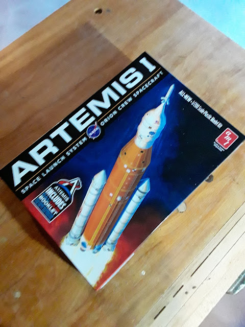
Artemis I, Part I -The Kit

To start off, this post will highlight what can be found when you open the box. Nice artwork, by the way.

The kit retailed at $34.95 plus a little on the side for the governor and mayor.  Sheesh, plastic models have become pricey these days

First, and most important are the molded styrene plastic parts. The model consists of thirty-eight pieces including the display base.

The model is 1:200 scale, placing it at the same size as Estes' RTF version.

Which brings up the question: why even bother with a plastic model conversion when a perfectly fine flying model can be readily had?

The thrill of the engineering and build process would be my best guess.

Moving on...

The decal sheet - many, many tiny decals.

Boomers, break out those lighted magnifier headsets. This ain't gonna be easy!

The instruction sheet - very minimally marked and illustrated, with not very much in the way of textual information.

Hang on to that box!   

 It turns out that the side panels contain a lot of information that normally would be on the instruction sheet.  Things like  overall parts ID, decal placement, and painting information.


Worth it's weight in gold...!

This refers to the small information booklet that is included with the kit. It is chock full of information about the Artemis/Orion vehicles and missions, illustrated with lots of great photos and diagrams.


Again, for those with less-than-sterling eyesight, a magnifying device may be necessary. That print is small!

More to come...

Monday, March 4, 2024

New Project - Artemis, Block I Plastic Model Conversion

 A visit to Colpar's HobbyTown store in Aurora, Colorado this past Friday netted a new kit that may prove to be an interesting build adventure for the BlastFromThePast shop.

This is the AMT Artemis I in 1/200 scale.

The model will be built simultaneously alongside some of the previously started 'binge-build' and repair-box models strewn about the workbench.

The difference with the Artemis is that I intend to post a full build series here.

I've only built one other plastic conversion kit in my model rocketry 'career', that being a Hawk Juipter-C (Juno-1) back in the late 1970s. It was quite successful, having turned in several great flights.

 Since there will be a bit of engineering going into the Artemis kit conversion, it will be a fun and challenging build.

I have already been perusing through a number of plastic model 'how-to' articles and videos online to familiarize myself with the finer points of PM building techniques.

If anyone out there reading this upcoming build series has any helpful hints and tips, I welcome you to weigh-in in the comments section.

A note of interest: 

My rocketeer buddy and across-the-street neighbor, Mike Perreault, picked up one of these kits as well.  This will enable us to do something that NASA will never accomplish-a simultaneous launch of two Artemis rockets, drag race style!

Cheers!